What I did in 8-weeks-VSD Internship? – Open Source Power Analysis Tool Using Python
Power analysis has materialized as a principal theme in today’s world in semiconductor industries. As very large scale integrated circuit (VLSI) are far beyond from human ability because of complexity in nature. So to analyse power in these circuits we use open source computer aided tools, plenty of tools are available but most of them are costly. I designed an open source power analysis tool for the academic use. This tool gives out values of average and leakage power of any circuit by just giving the netlist of circuit file along with name of supply voltage as input. This tool is designed in python language.
POWER ANALYSIS
Power analysis of design can be reconnoitred at several levels such as system level, architectural level, logic level, circuit level and device level. Power analyser is a tool which determines how much power is utilize by a system or circuit. On the basis of study, design cycle of a typical power analysis in different stages is as shown in “Fig. 2”.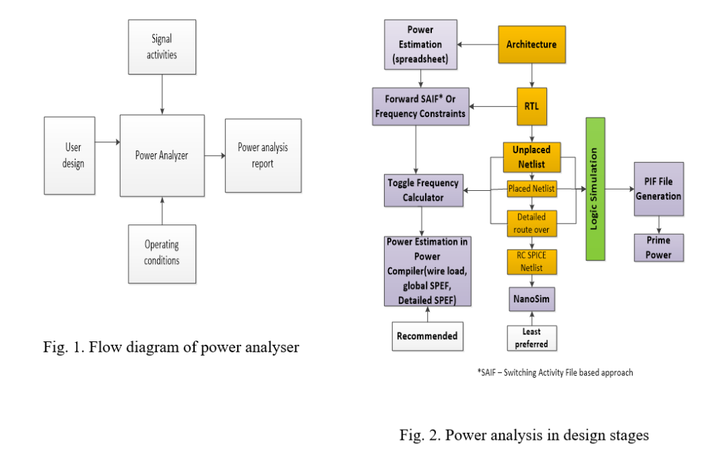
POWER DISSIPATION BASICS
In CMOS circuits there are mainly three types of power dissipation namely average power dissipation, short circuit power dissipation and leakage power dissipation.
1. AVERAGE POWER DISSIPATION
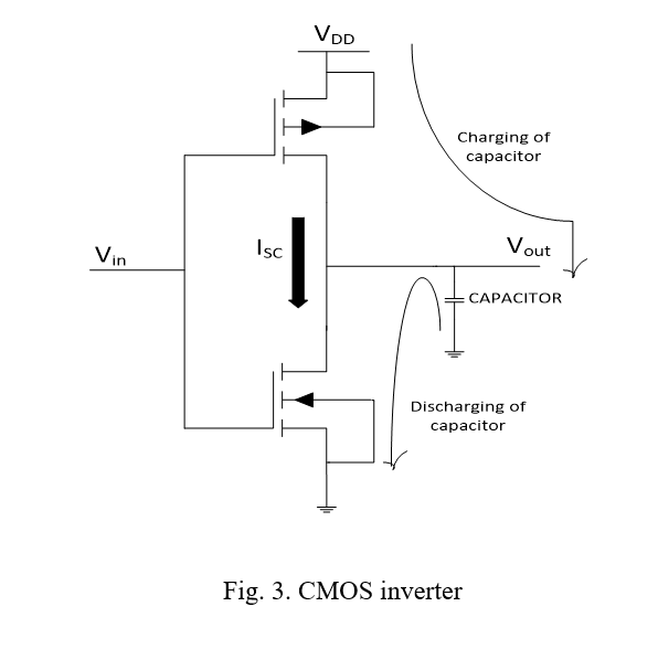
This power is also known as switching or dynamic power dissipation. The significant cause of this power dissipation is switching or we can say that it occurs during charging and discharging of capacitance as shown in “Fig. 3”. Dynamic power can be obtained from the formula as in equation 1.
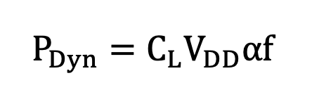
…(1)
Where CL is load capacitor, VDD is supply voltage, α is switching activities factor of a circuit and is the clock frequency. To evaluate average switching power in charging and discharging of a capacitor we have to integrate the power required to charge the capacitor from VDD through PMOS and discharging to ground through NMOS while applying the input voltage having zero rise and fall time of time period T.
2. SHORT CIRCUIT POWER DISSIPATION
During switching there is some small time when both PMOS and NMOS are ON and there is short circuit current flow from VDD to ground as there exist a path between them as shown in “Fig. 3”. This power dissipation arises because practically input voltage pulse has some finite rise and fall time.
3. LEAKAGE POWER DISSIPATION
(i) SUBTHRESHOLD LEAKAGE POWER DISSIPATION
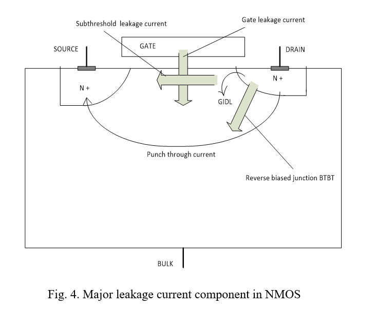
When gate voltage is less than threshold voltage of MOSFET then even a current flow from drain to source through channel because of drain voltage (VDS) this current is called as Subthreshold Leakage Current as shown in “Fig. 4”. It causes dissipation of power known as subthreshold leakage power dissipation.
(ii) GATE-OXIDE TUNNELING LEAKAGE POWER DISSIPATION
In short channel devices, resultant of electric field of gate voltage electric field and drain voltage electric field causes electrons to move in zig zag manner and some electrons which gain extra energy at pinch off tunnel to gate through insulating SiO2 layer. This gives to gate leakage current towards substrate as shown in “Fig. 4”. It causes dissipation of power known as gate oxide tunnelling leakage power dissipation.
(ii) REVERSE BIASED JUNCTION BTBT POWER DISSIPATION
It occurs when the source or drain of an NMOS is at VDD or in case of PMOS is at ground. Reversed biased PN diode is formed at source or drain of transistors causing flow of current through substrate as shown in “Fig. 4”. In this process tunnelling of electron of p type substrate from valence band to conduction band of n type drain occur. Hence, this current is known as Reverse Biased Junction BTBT Current. It causes dissipation of power known as reversed biased junction BTBT power dissipation.
STRATEGY OF POWER ANALYZER TOOL
The strategy that is used in the tool presented is as follows:
A. CALCULATION OF AVERAGE POWER DISSIPATION
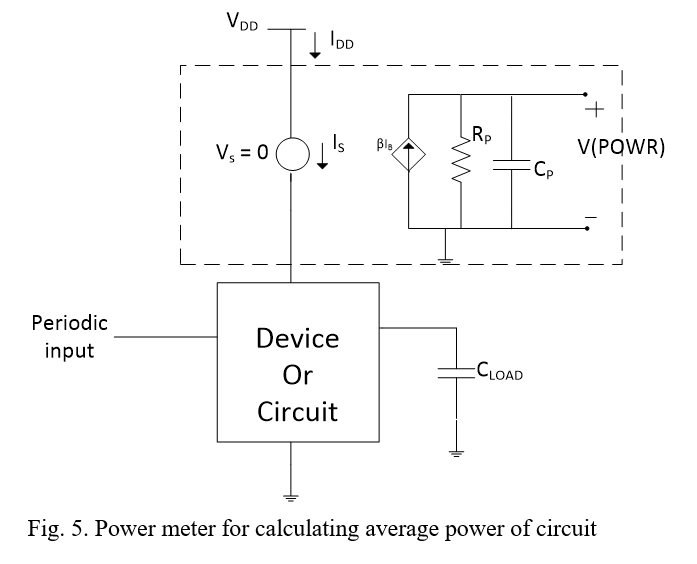
Placed a power meter between power supply and device as shown in “Fig. 5” and calculate the product of average current and Voltage. For calculating average current, I placed one extra power source of 0V in netlist.
Power meter consists of a current controlled current source (βIB) and voltage steps across this during time period is average power. Voltage steps of V(POWR) is same for every time period (T). The value of β can be obtained as CPVDD/T.
B. CALCULATION OF LEAKAGE POWER DISSIPATION
Remove all non-constant power supply voltages and calculate the product of leakage current and Voltage. For calculating leakage current, I placed one extra power source of 0V in netlist.
INPUTS FOR POWER TOOL
Following things are needed for user to enter while executing the tool
- Netlist file.
- Name of supply Voltage.
iii. Time period, if circuit is synchronous then clock pulse time period or in case of asynchronous minimum time period among all inputs.
DEPENDENCIES OF POWER TOOL
For execution of this tool we need ngspice and python only. Ngspice is an open source mixed signal circuit simulator.
DESCRIPTION OF CIRCUIT USED FOR POWER TOOL
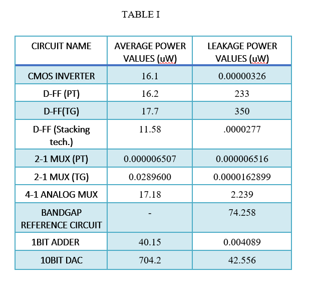
For the analysis of my power analysis tool I Simulate D flip flop using pass transistor, transmission gate, pass transistor with stacking of transistor as shown in “Fig 6-8”. 2-1 MUX using pass transistor, transmission gate, as shown in figure 9-10. Along with these circuits I also analyse the power of 4 input analog multiplexer circuit, band gap reference circuit, 1bit adder circuit, 2 bit analog to digital converter and 10 bit analog to digital converter circuit. Takes netlist and calculate average and leakage power values of circuits from tool presented in this paper. All obtained values from tool are tabulated in table 1.
![]()
![]()
![]()
![]()
![]()
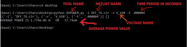
USE PYTHON SCRIPT TO FIND AVERAGE POWER
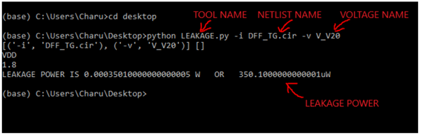
USE PYTHON SCRIPT TO FIND LEAKAGE POWER
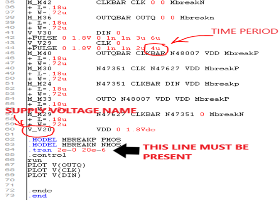
NETLIST (To show which values to be entered while running script)
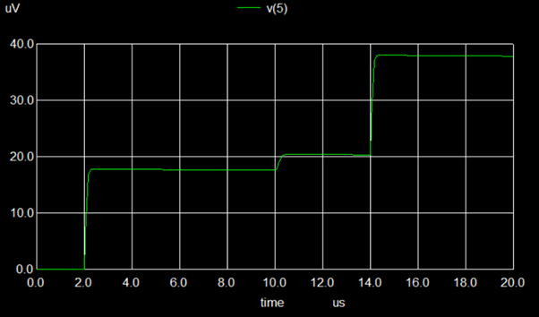
Power plot
Following average power graph we get on NGSPICE when we run modified script that we get from tool.
OUTPUT OF TOOL FOR CIRCUITS
All evaluated values of average power and leakage power of circuits from the tool designed using python are tabulated in table 1.
FUTURE WORK
For proper working of this tool circuit must have single power supply source. Hence it can be modified so that it works for multiple supply voltages.
Detailed Reference and Source Code can be found here — https://github.com/CharuGupta-eng/vsdOSPowerCalc
![]()
