I am talking about recent webinar which we did using Proton, with Rajeev. And he demonstrated how you can do entire physical design using Proton on cloud. Here are few steps to do it
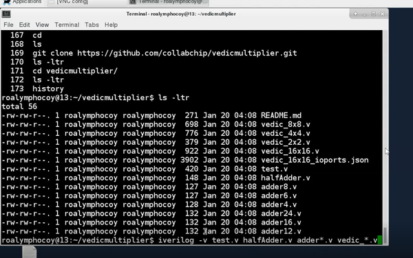
First you can do a quick functionality using i-verilog. Below image shows the list of RTL files. It’s a hierarchical design. To make-up a 16×16 multiplier, we use 8×8, 4×4, 2×2 hierarchy multipliers. test.v is the test-bench that instantiates vedic16x16 and has some of the tests written to it, meaning we are giving some inputs and observing the outputs. Below image also shows the command to run iverilog:
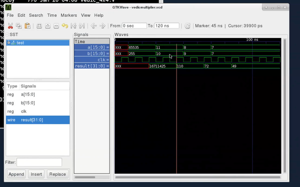
Once you run it, you will see a compiled file “a.out” and now you can run the compiled file using the below command:
./a.out
Now a vcd file is available. To view the vcd file, we will use a tool called gtkwave. See below image for ‘a’ input as 11 and ‘b’ input as 10. On first clock edge, the inputs are registered and on the second clock edge, result (110) is available
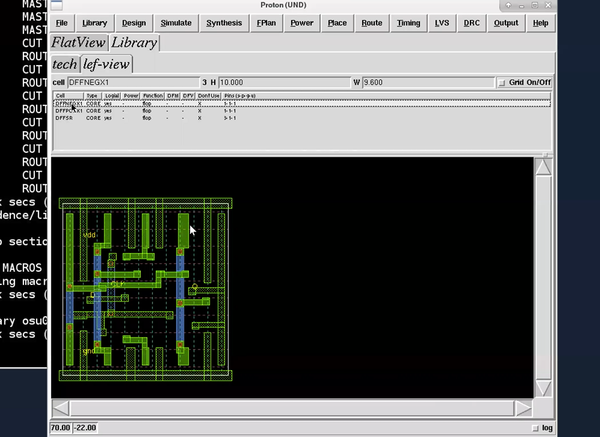
Now first step, where you import all your libraries, which includes timing libraries and LEF files, you can use the LEF viewer feature of Proton to view LEF files and see internal layout of your standard cells. The steps are easy, you just need to type DFF is the “cell” box seen in below image, select a cell and you will see how the standard cell is layed-out, just as shown in below image
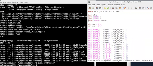
Next step is synthesis, where you import RTL and bind RTL with your standard cells. In this step, we will use qyosys and below is a snippet of synthesized netlist:
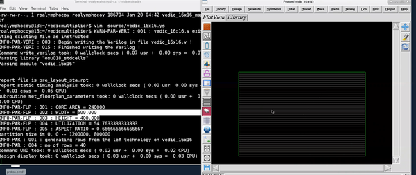
 Now you will define the aspect ratio by fixing the width and height of core and die. And below image shows the first level floorplan with width, height, aspect ratio and utilization factor highlighted.
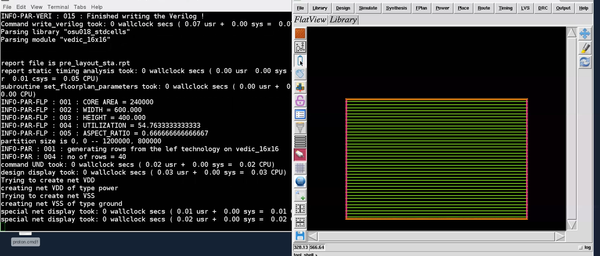
Next step is to add power. When we synthesize the design, there are no power nets. So, we will first create power nets. You can call them VDD, VSS. This will create 2 new nets in the design. Then, we need to create a ring around the block. Ring is typically created in the top-most layer available to us. We will use metal5 horizontal and metal6 vertical with 2um width and 1um spacing.
Next step is to create power rails. Now power rails are generally in lowest metal layers. We will use metal1 and width should match the standard cell rail width that we have, so we will use 0.6um. Below image is how power rails will look like:
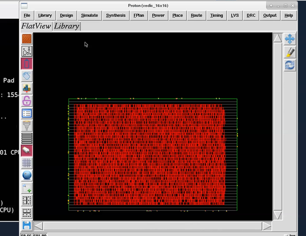
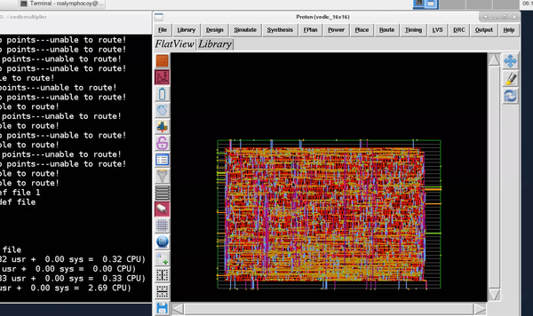
Then, finally we will use Graywolf for placement and Qrouter for routing. The below 2 images shows how placed and routed netlist looks like:
he above blog demonstrates the whole flow. But in case you are looking for explanation on each step, you might want to check out our recently conducted webinar on Physical design with EDA tool Proton. Here’s the link/image for the same:
https://www.udemy.com/vsd-physical-design-webinar-using-eda-tool-proton/
And there’s something more. If you learn this tool and use it to build your own applications, you might end up presenting a paper in our online conference happening soon called “VSDOpen” – The first ever online conference on opensource EDA. Will talk about it further blogs. So get ready for it…
All the best and happy learning….
