Hi
“All that glitters is not gold”…. Similarly, “All that bumps is not noise”…. This is what needs to be nailed forever
While doing my static noise analysis, I always bumped over the fact that if noise height or voltage are too high to create a bump, then why sometimes it doesn’t impact the entire circuit. I also have heard of explanations about CMOS inverter being acting as a low pass filter, so it just ignores sharp transitions, and many more which created even more confusion to me as a beginner, some 7 years back So, for everyone and every fresher facing similar confusion, let me resolve it once and for all. Here’s the thing. Let’s take the same circuit (which I used in my Signal integrity course) and execute it in SPICE, like below:
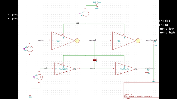
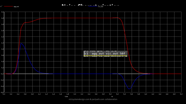
The bottom set of inverters form the victim line, while the top set of inverters form the aggressor line. I added a coupling capacitor of 50f between the aggressor and victim. I have also provided the pulse waveforms at aggressor and victim inputs, and once we simulate it, we get something like below: In real scenario, the coupling capacitance of 50f will be extracted from layout based on routing. Over here, we are modelling it
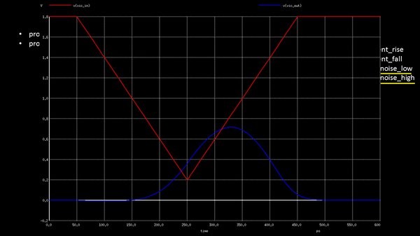
Taking a closer look at the blue bumps on victim lines, I tried to find out 2 extreme situations with noise height being kept constant, while varying only the noise width. For a noise height of about 1.6v and noise width of about 400ps, while keeping output capacitance as 10f, I see a reasonable bump at the victim line, which proves the fact that noise height indeed plays a very important role in determining glitches
But when I kept noise height and capacitance constant, while varied only the noise width from 400ps to just 100ps, to my notice, I saw the bump actually got minimized, almost negligible. See below image:
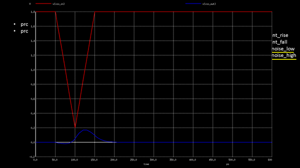
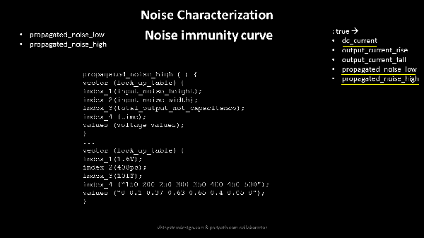
Now why is this so? So if you change a waveform so fast within a shorter period of time, by the time the victim line reacts to the glitch, by charging itself from logic ‘0’ to logic ‘1’, the aggressor comes back to its original state, thus not giving the victim enough time to charge, and hence it comes back to its original position. Thus, proving the fact, that inverters are, indeed, low pass filters, not allowing fast changing signals or high frequency signal like the above to impact victim. And hence, we have propagated noise tables (commonly called as noise immunity curves) as a function of noise width, noise height and output capacitance. The way its modeled is shown below:
So, something in favor of aggressors, “Never judge someone by the opinion of another”.
