Overview
This project aims to design and implement a 2-bit comparator using the VSDSquadron Mini board. A 2-bit comparator is a digital circuit that compares two 2-bit binary numbers and indicates whether one number is greater than, less than, or equal to the other. The project involves designing the comparator logic using C programming in Visual Studio Code, setting up the hardware connections on a breadboard, and verifying the functionality through LEDs connected to the output.
Project Objective
The objective of this project is to:
- Design a 2-bit comparator using C programming.
- Implement the designed comparator on the VSDSquadron Mini board.
- Verify the correct functionality of the comparator by using LEDs to display the comparison results.
- Gain hands-on experience in digital circuit design, C programming, and hardware implementation.
Key Components
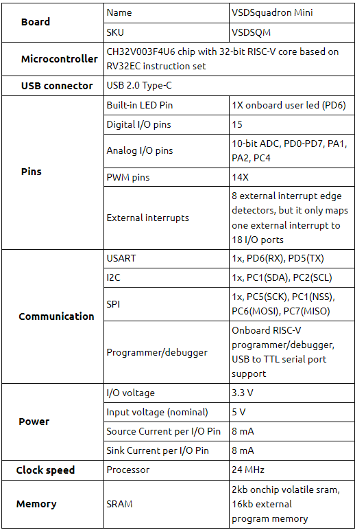
- VSDSquadron Mini Board : The main microcontroller board used for processing and logic implementation.
- Breadboard and Jumper Wires : For building and testing the circuit.
- LEDs : To display the comparison results.This project requires 3 LEDs.
- Resistors : To limit the current to the LEDs.220Ohm resistors are used in this project.
Pin Configuration
| LED | VSD SQUADRON BOARD |
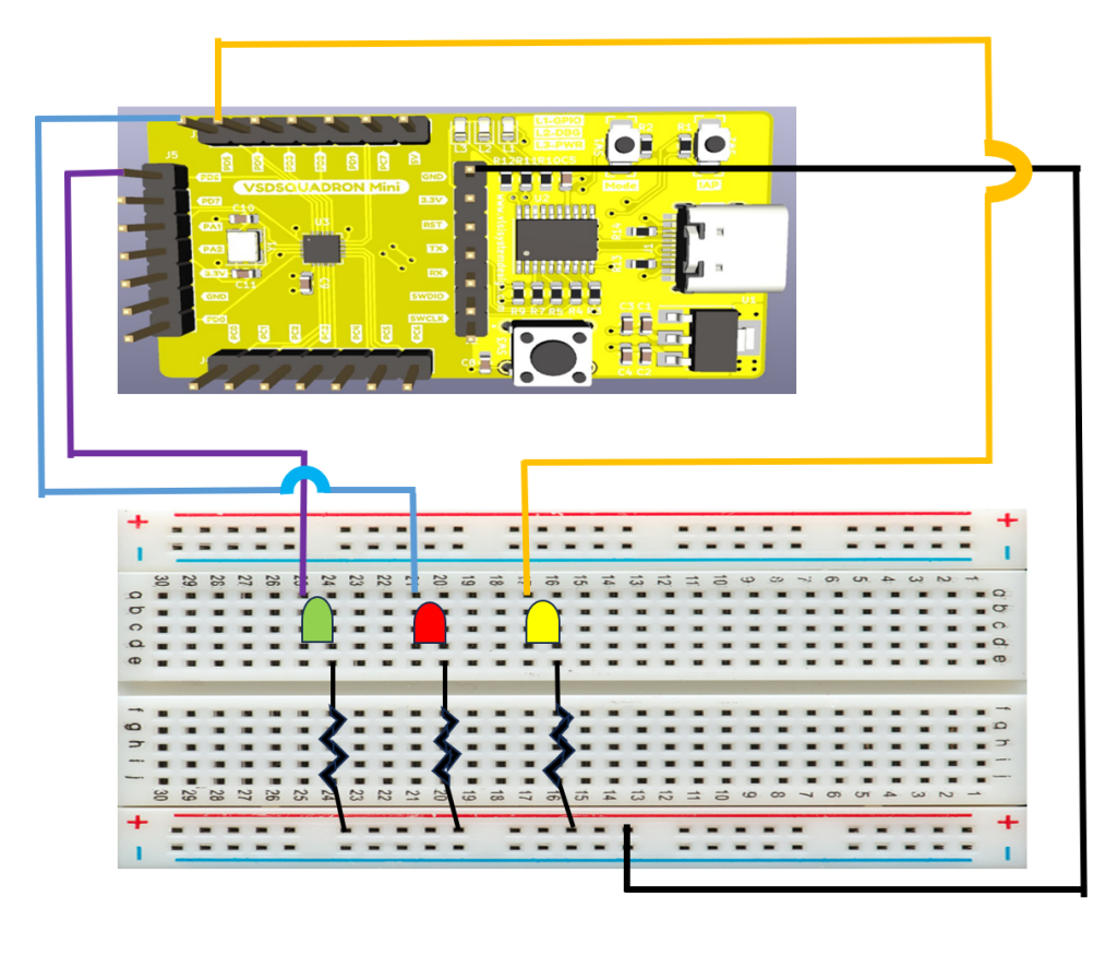
| LED1 | PIN4 (PD4) |
| LED2 | PIN5 (PD5) |
| LED3 | PIN6 (PD6) |
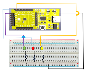
Circuit Diagram

Functional Description
- A > B: LED1 (Yellow color) lights up when a is greater than b.
- A < B: LED2 (Red color) lights up when a is less than b.
- A = B: LED3 (Green color) lights up when both numbers are equal.
Truth Table of 2-bit comparator
| A1 | A0 | B1 | B0 | A>B | A=B | A<B |
|---|---|---|---|---|---|---|
| 0 | 0 | 0 | 0 | 0 | 1 | 0 |
| 0 | 0 | 0 | 1 | 0 | 0 | 1 |
| 0 | 0 | 1 | 0 | 0 | 0 | 1 |
| 0 | 0 | 1 | 1 | 0 | 0 | 1 |
| 0 | 1 | 0 | 0 | 1 | 0 | 0 |
| 0 | 1 | 0 | 1 | 0 | 1 | 0 |
| 0 | 1 | 1 | 0 | 0 | 0 | 1 |
| 0 | 1 | 1 | 1 | 0 | 0 | 1 |
| 1 | 0 | 0 | 0 | 1 | 0 | 0 |
| 1 | 0 | 0 | 1 | 1 | 0 | 0 |
| 1 | 0 | 1 | 0 | 0 | 1 | 0 |
| 1 | 0 | 1 | 1 | 0 | 0 | 1 |
| 1 | 1 | 0 | 0 | 1 | 0 | 0 |
| 1 | 1 | 0 | 1 | 1 | 0 | 0 |
| 1 | 1 | 1 | 0 | 1 | 0 | 0 |
| 1 | 1 | 1 | 1 | 0 | 1 | 0 |
Code for implementation of 2-bit comparator using VSDSquadron Mini Board(.C Code)
#include <ch32v00x.h>
#include <debug.h>
#include<stdio.h>

#define LED1_PIN GPIO_Pin_4 //yellow LED
#define LED2_PIN GPIO_Pin_5 //red LED
#define LED3_PIN GPIO_Pin_6 //green LED
#define LED_PORT GPIOD

void GPIO_Config(void) {
    // Enable the clock for GPIOD

    RCC_APB2PeriphClockCmd(RCC_APB2Periph_GPIOD, ENABLE);

    // Configure PD4, PD5, and PD6 as outputs
    GPIO_InitTypeDef GPIO_InitStructure;
    GPIO_InitStructure.GPIO_Pin = LED1_PIN | LED2_PIN | LED3_PIN ;
    GPIO_InitStructure.GPIO_Mode = GPIO_Mode_Out_PP; // Push-pull output
    GPIO_InitStructure.GPIO_Speed = GPIO_Speed_50MHz;
    GPIO_Init(LED_PORT, &GPIO_InitStructure);
}

void compare_2bit(uint8_t a, uint8_t b) {
    // Clear all LEDs
    GPIO_ResetBits(LED_PORT, LED1_PIN | LED2_PIN | LED3_PIN);

    if (a > b) {
      // Light up LED1 if a > b
        GPIO_SetBits(LED_PORT, LED1_PIN);
    } else if (a == b) {
        // Light up LED2 if a == b
        GPIO_SetBits(LED_PORT, LED2_PIN);
    } else {
        // Light up LED3 if a < b
        GPIO_SetBits(LED_PORT, LED3_PIN);
    }

}

int main(void) {
    NVIC_PriorityGroupConfig(NVIC_PriorityGroup_2);
    SystemCoreClockUpdate();
    Delay_Init();
    // Initialize the GPIO for the LEDs
    GPIO_Config();


    // Main loop to iterate over all possible 2-bit numbers
     for (uint8_t a = 0; a <= 3; a++) {
        for (uint8_t b = 0; b <= 3; b++) {
            compare_2bit(a, b);
            Delay_Ms(5000); // Delay for visualization
        }
    }

    return 0;
}
Project Demonstration
Conclusion
This implementation demonstrates the use of the VSDSquadron Mini board to design a basic digital circuit. The 2-bit comparator effectively compares two binary numbers and outputs the comparison results through LEDs. This project reinforces the fundamental concepts of digital design.Overall, this project was a valuable learning experience.
Related Posts:
- Home safety system
- Shape Tomorrow’s Technology Today: ELCIA Hackathon…
- Secure Saiyan
- RISC-V Mini Game Console
- Motion Detection System Using PIR Sensor and…
- LED Brightness Control Program using PWMLED…
- LiFi Lock - An authentication system using LiFi…
- t1tan-strik3rs
- Smart Plant Care using the VSD_Squadron-MINI-BOARD
- COLORIMETER


