Hey There – Think about it!!
Today’s version of open-source EDA tools, work very well for hierarchical designs sub-25k instance count. For hierarchical designs ~500k instance count, develop code which will enable users to connect pre-placed power pins to power rings around them and generate power grid within core
Inputs given for code development and testing:
- A text file in DEF format with clear definitions of core/die width, pad placement, pre-placed cells, power rings around core/pre-placed cells and other information unplaced/placed/fixed cells
- Industry grade 180nm PDK’s (standard cells, memories, pads) LEF formats
Expected output:
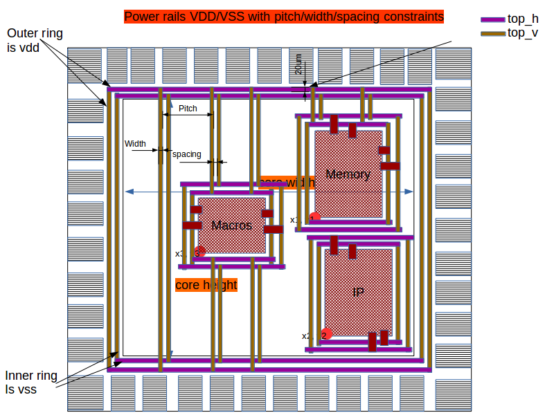
A text file in standard DEF format which has all information about inputs which were provided + information about pre-routes and power grids (shown in below image)
Step 1) Find a way to parse input DEF file, which has locations, co-ordinates, instance names and many more information of all instances that you see in below image. It can be a command something like below
read_def <input_def_file>
If the DEF file syntax is not in par with standard DEF syntax, issue an error message specifying line number where there is a syntax error
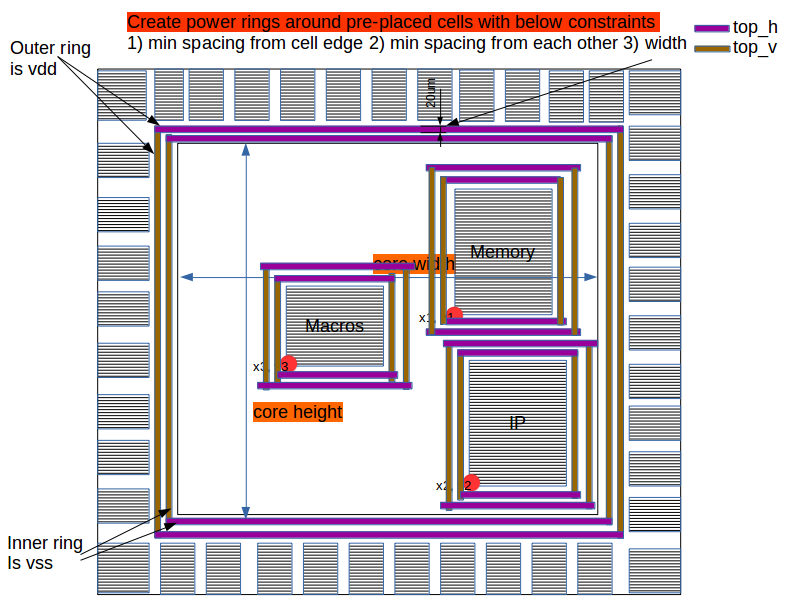
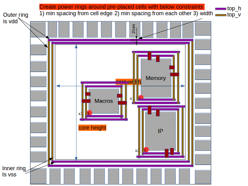
Step 2) Develop code (or command) connect memory/ip/macro power pins to main power grid (See below image for description)
It can be a command something like below
connect_pre_placed_cells_vdd_vss_to_power_grid
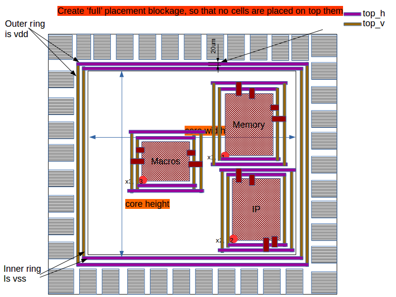
Step 3) Develop code (or command) to create placement/routing blockage on macro’s/IP’s/memories OR any pre-placed cell so that automated placement/power routing/signal routing tool should not place any cell on top of pre-placed cells or route on top of these cells (See below image for description)
Keyword “BLOCKAGE” is used to define in DEF file (Look up for industry DEF file formats)
It can be a command something like below
set ip_cordinate [get_my_property <ip_instance_name> cordinates]
The above command will set a variable $ip_cordinate = {x y}
create_blockage -blockage_cordinates $ip_cordinate
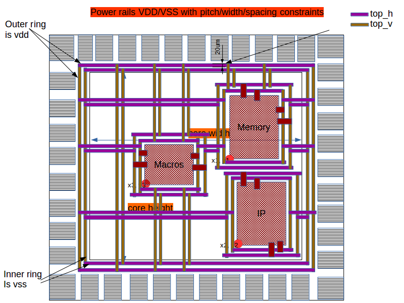
Step 4) Develop code (or command) to create power grid inside core, starting and ending, from and to power rings around core boundary (See below image for description)
It can be a command something like below (V = Vertical, H = Horizontal))
create_power_grid -direction V -width <number_in_um> -net_names {VDD} -pitch <number_in_um> -layer_name <top_vertical_layer> -start_location <x_location_for_vertical_power_strip>
create_power_grid -direction V -width <number_in_um> -net_names {VSS} -pitch <number_in_um> -layer_name <top_vertical_layer> -start_location <x_location_for_vertical_power_strip>
create_power_grid -direction H -width <number_in_um> -net_names {VDD} -pitch <number_in_um> -layer_name <top_horizontal_layer> -start_location <y_location_for_horizontal_power_strip>
create_power_grid -direction H -width <number_in_um> -net_names {VSS} -pitch <number_in_um> -layer_name <top_horizontal_layer> -start_location <y_location_for_horizontal_power_strip>
Terms and condition:
- You are free to use the source code of existing (and only) opensource tools like magic, qflow, graywolf, qrouter.
- Each line of your code needs to be open-sourced and documented
