Hello,
I have been receiving multiple queries on what is clk-to-q delay, how’s it different from library setup time and library hold time, etc.
I mentioned in my discussions, that the videos on CMOS digital circuit will be uploaded soon, but looks like, it might take some time, and hence decided to uploaded few images from my CMOS course, to explain the difference between all of them.
We will learn about it in two parts. This post will explain what is present inside the flipflop i.e. negative and positive latches, and the transistor level implementation of both.
In next post, we will explain, how a positive edge triggered flp flop is made using positive and negative latches, and come up with equations and differences between clk-to-q delay, library setup time and library hold time
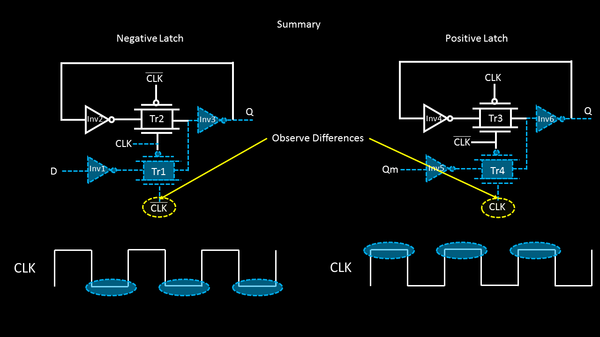
Let’s begin with the first image which shows what’s present inside flip flop and introduction to negative latch
check out the below series of images.
Hope these set of above images, clearly distinguishes what’s a positive latch, what’s a negative latch and what happens when clock is ‘low’ or ‘high’. I would say glance through the images one more time, so that the concept is clear.
In my next post, I will connect the output of negative latch to input of positive latch, and throw some light on clk-to-q delays and the setup and hold times internal to flip flops
I would also like to request everyone to share their experiences/doubts in this post
Happy Learning
Thanks
VSD Team


![]()
![]()


![]()
![]()