Hi
read_sdc is been considered as a very critical command in EDA world, as this is the command which defines your specifications, and if not written and interpreted correctly, can lead a huge delay in tapeout cycle. While a lot goes into the making for this proc (I know since I already have worked for an EDA company), I have written one to map this command with open source STA tool Opentimer.
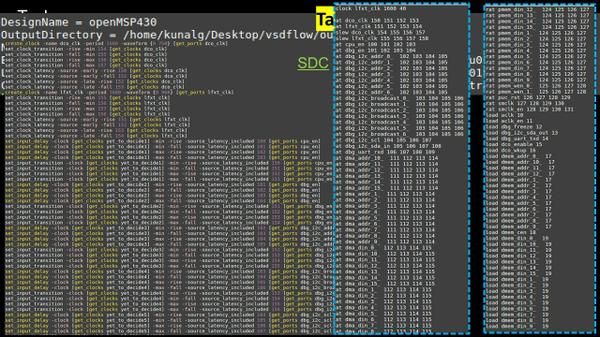
The job of read_sdc is to convert any SDC command to an internal STA tool command. The STA tool can be anything. It’s the job of the respective EDA vendor, that it maps SDC command to its STA engine and interpret it correctly. Below image sums it all –
Let’s take an example of clock constraints, and the same (more or less) can be mapped to input and output constraints.
create_clock constraints –
The critical part of this constraint is how Opentimer interprets duty cycle. In below image, the clock keyword denotes the single clock signal <PI> of the design. The <clock period> is a decimal specifying the total time of one rise and fall transition of the clock signal. The <low %> is decimal specifying the percentage of <clock period> where the clock signal is low. By default, the clock signal starts low and rises at the appropriate time. For example, if <clock period> is 1600ps and <low %> is 40, then the clock signal rises at 640ps
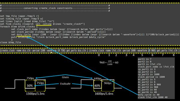
This is resolved using the ‘expr’ TCL command, on elements indexed shown in above image. This is needed, because the way we define duty cycle in SDC command “create_clock” is exactly reverse
Next, let’s look into clock latency command:
set_clock_latency constraints –
set_clock_latency command maps to ‘at’ command internal to Opentimer, shown in below image. The at keyword denotes the arrival time at a primary input <PI>. The <early rise at> field specifies the early rise arrival time of <PI>. The <early fall at> field specifies the early fall arrival time of <PI>. The <late rise at> field specifies the late rise arrival time of <PI>. The <late fall at> field specifies the late fall arrival time of <PI>.
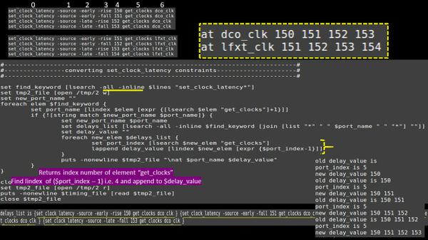
The above TCL snippet collects all latency elements of “set_clock_latency” command for a particular clock, arranges it in horizontal format, and appends the clock port name and ‘at’ keyword.
Finally, we have clock transition command.
set_clock_transition command –
set_clock_transition command maps to ‘slew’ command in Opentimer, shown in below image. The slew keyword denotes the input slew at <PI>. The <early rise slew> field specifies the early rise slew of <PI>. The <early fall slew> field specifies the early fall slew of <PI>. The <late rise slew> field specifies the late rise slew of <PI>. The <late fall slew> field specifies the late fall slew of <PI>.
The only difference between set_clock_latency snippet and above set_clock_transition snippet is the search keyword and append keyword. This time, as highlighted above, its ‘set_clock_transition’ and ‘slew’
The above TCL read_sdc proc do prove that ‘Learning is FREE’. The recent critics on my style of learning – that I do not use standard EDA tools for teaching – can be resolved by just writing procs for important commands using open source EDA tools, and provide a EDA similar user interface.
So you have commands now, you know how to create these commands and you know how these commands behave in real world. What else you need, name it, and I will build something around it
Really Thankful to all of you for your wonderful feedback that’s helping us to push our limits and create something new…Appreciate your efforts to help us
