Hey There
We all must have read blogs and watched videos about how to convert a decimal floating-point number to its binary form. We must have seen standard formulas of converting an IEEE754 standard floating-point number to its decimal form.
Well, this blog points out the inception of how the IEEE754 floating point standard designed the way it is. Every great design begins with an even better story. I have covered the detailed story behind design of IEEE754 floating point standard in below (pre-launched) course, but let me summarize in brief about it in this blog
https://www.udemy.com/vsd-riscv-instruction-set-architecture-isa-part-1b/
Cutting long story short, the basic floating-point representation is shown in below image:
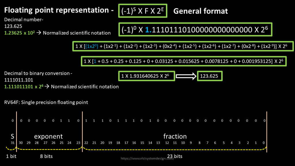
The missing point over here was the explicit mention of “1.” which always needs to be taken care of while converting any number from binary to decimal. Else, you miss the accuracy by half.
For e.g., had we missed converting “1.” In above image (i.e. remove (1 x 20)) from above conversion, and the number which you obtain is “59.625”, which is half of the number what we expect it to be. That’s a 50% loss in accuracy – huge
Next, the idea was to make “1.” As implicit in floating point standard itself. And that was the birth of IEEE754 floating point standard, which looks like the one shown in below image:
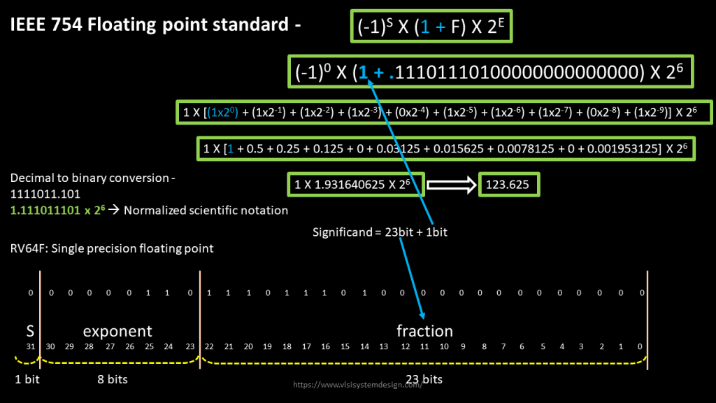
Make “1.” implicit in standard itself, and this was the inception of having “1+F” in the floating-point standard definition. Next problem was from a hardware point of view. Let’s say if you want to subtract a very large number from a very small number, the large number should be look a large number and the small should look small. Manually detecting this, and making hardware compatible to this, was a real pain.
Somebody jokingly had said, “If you find a operational bug in a chip after tape-out, change the documentation”. Well, something similar was done here. The operational problem with this IEEE form is shown in below image:
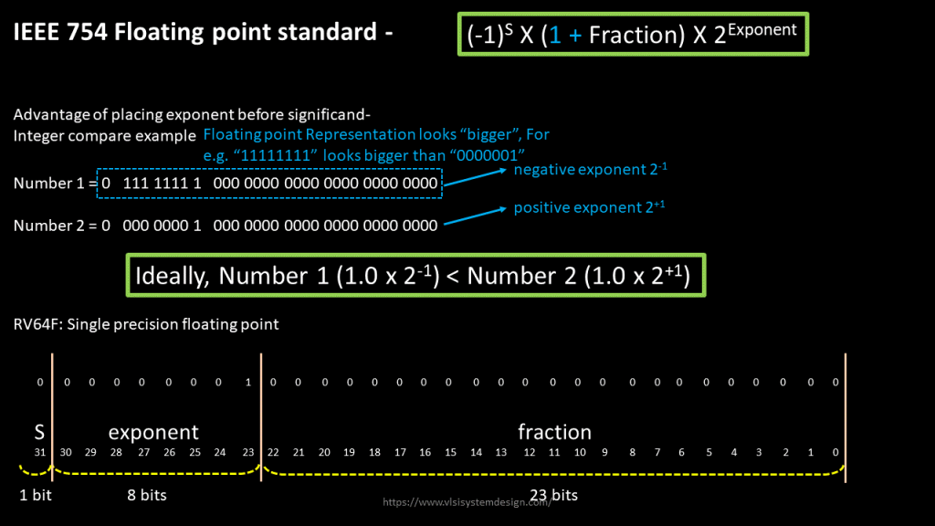
A number with 2-1 exponent should look smaller than a number with 2+1 exponent. But that was not the case with existing IEEE format. The desired representation would be all ‘1’s for most positive number and all ‘0’s for most negative number, like 0111 1111 for most positive (since exponent field is 8bits, with highest bit reserved as “sign bit”) and 0000 0000 for most negative.
That’s called ‘bias’ which is 127 (0111 1111) for RV64F case. That modifies the IEEE754 floating point standard from above to below image:

Now, to represent negative exponent of “-1”, you just need to add “bias” of 127 to it (-1 + 127 = 126) and 126 is what needs to present in exponent field, in its binary form. Similarly, to represent positive exponent of “+1”, you need to add bias of 127, which makes exponent as 128, and that’s what will go in the exponent field.
Now investigate the above numbers. Number 1 looks smaller than number 2, due to ‘1’ in MSB of exponent field in number 2. That’s the story. Now try converting any decimal floating-point number to its binary form. Not only that you will learn conversion, but you will enjoy it because now you the inception of the standard
If you want to hear more about the story of RISC-V architecture, its inception and its connection with above IEEE754 standards, you might want to enroll into below 2 courses on RISC-V:
RISC-V ISA Part 1a:
https://www.udemy.com/vsd-riscv-instruction-set-architecture-isa-part-1a/
RISC-V ISA Part 1b (pre-launch):
https://www.udemy.com/vsd-riscv-instruction-set-architecture-isa-part-1b/
All the best, enjoy the stories and happy learning….
