
Hello,
And that’s what I aim in my new course (yet to be released)
Let me try to give you a basic snapshot of what the course is going to be all about
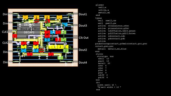
Custom or handmade layouts, which is the basis of standard cells/macros/IPs, are generally based out of set of lines written in a certain fashion in a file called as ‘tech file’
In a nutshell, the standard cells you see on below chip on the left hand, can be built using the text written on right side and open source Magic tool.
Good news … You can practice custom layouts for FREE….
Great news .. You can build your own design or IP using open source tools (Magic to start with)… Stay along with me and I will tell you exactly how to do it
Look into the below layout of CMOS inverter (why CMOS inverter? Its the most common logic being used for building most of the standard cells)
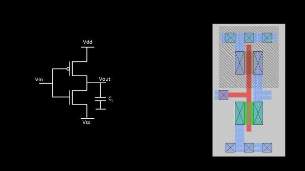
The minimum lines needed to draw the above layout (and in correct syntax), is as shown below:
We will have the “planes” section first to define ‘planes’ ‘names’ such as ‘active’ plane to define the active region where transistor is being placed, ‘well’ plane to define the nwell or pwell where we would build the transistors, and ‘metal1’ plane to define metal layer plane for power/ground lines
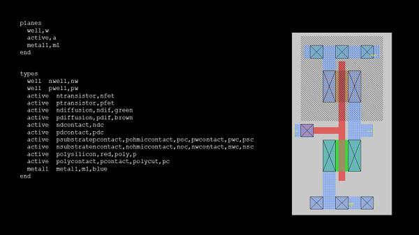
The types of planes, like m1 is or type ‘metal1’ plane, nwell is of type ‘well’ plane, etc. are defined under ‘types’ section. I will get back to details of each one of them in my course
Next is to give some style or colors to the planes and each type of plane. Its provided under the ‘type’ section of tech file as shown below:
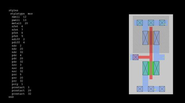
Don’t worry about the code number in from of nwell, pwell, etc. I will talk about it in my course. You can think of it as some code for a color, 1 – for Red, 2 – for Blue, etc. (these are just examples)
Finally, the most important one, DRC rules. It usually comes from foundries and it takes an exorbitant amount of paper work and licenses to use them.
We have a workaround — Let’s write and code our own DRC rules (Assuming we are getting it from, say, ‘myFoundary’ located somewhere in Poland, may be :)) This will be good enough to understand the concepts and get started with open source tools
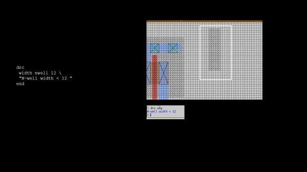
In above simple example, ‘myFoundary’ from Poland, gave me a rule saying NWELL width has to be atleast 12 units (units are usually ‘lambda’, and I will talk about it more).
So I code my tech file to take care of this rule and if, for some reason, the nwell width goes below 12units or 12 lambda, Magic will inform or return an ERROR to me saying “N-well width < 12”, please correct it.
That’s it. Simple, isn’t it.
I can promise you, using open-source right from making layouts to building products will be a journey never forgotten
Happy Learning !!!
