Floorplanning
Floorplanning is basically the arrangement of logical blocks (i.e. multiplexer, AND, OR gates, buffers) on silicon chip.
Consider a large design like microprocessor. The abstract level behavioral description of the processor is written using an RTL program. Large designs (e.g. microprocessor in our case) are usually synthesized into small modules. These modules are the basic building blocks of a microprocessor e.g. memory unit, adder/subtractor (ALU) unit, multiplexer unit, etc. Consider the following diagram
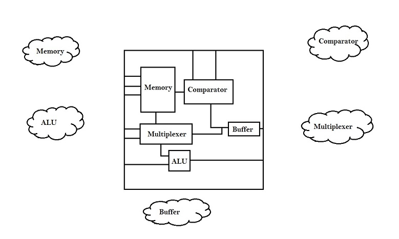
Modules are called as blocks, when it is assigned an appropriate area and aspect ratio (Height[h]/Width[w]). Blocks are usually classified as ‘soft’ and ‘hard’ blocks. In hard blocks, the area and aspect ratio of the blocks are fixed, whereas for soft blocks, the area is fixed but aspect ratio could vary. The placement of these blocks on a chip decides the size of the chip. This would be clear in the following diagram.
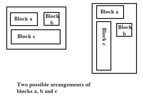
Consider, we have three blocks, a, b and c, as shown in above diagram. We have two possible arrangements of these blocks. The arrangement shown in left occupies minimum area, whereas the one on the right occupies larger area on chip, and hence facilitates the user to add more blocks (i.e. additional functionality) in to the chip. Now, of the above two arrangements, which one is selected, depends upon the end-user specifications. If, the specifications demands for minimum area, the left arrangement is selected, whereas, if the specification demands decent area as well as additional functionality, the second arrangement is selected.
Hence, floorplanning makes sure of 3 things :
1) Every module has been assigned an appropriate area and aspect ratio.
2) Every pin of the module has connection with other modules or periphery of the chip.
3) Modules are arranged in a way such that it consumes lesser area on a chip.
