Design Chip Area contest
Problem Statement– Today’s version of open-source EDA tools, work very well for hierarchical designs sub-25k instance count. For hierarchical designs ~500k instance count, participants are expected to develop code which will enable users to design/decide chip area based on width and height of chip OR utilization factor and aspect ratio of core.
On successful completion, participants with best results will win:
- Certification and recognition from IIT Madras RISC-V SHAKTI Team
- 1 LIVE webinar with VSD team on this topic with 50% Lifetime Revenue share
Inputs given for code development and testing:
- Full RTL code for SHAKTI RISC-V micro-processor in Verilog format
- Industry grade 180nm PDK’s (standard cells, memories, pads) in LIB and LEF formats
Expected output from this contest:
- A text file in standard DEF format which has all information (shown in below image) about the core and die
Does that sound easy? It is easy and proven for a flat design, so this ideally should be just an extension to that as SHAKTI RISC-V SoC, and practically all designs in the world, are hierarchical designs
Let me suggest you some steps to reach above point:
Step 1) Find a way to parse macro/memory/IP LEF’s and. libs provided by VSD. These files have all information regarding physical shapes & sizes, timing characteristics of all logic elements which will be used in design. It can be a command like below:
read_lef <list_of_all_lef_files> [you might want to refer to “lef read” command of MAGIC]
read_lib <list_of_all_lib_files> [you might want to refer to “read_liberty” command of yosys]
If lef file and lib file syntax is not in par is standard LEF and LIB syntax, issue an error message specifying line number where there is a syntax error
Find a way to parse synthesized hierarchical verilog netlist (about 300k instance count), which will be provided by VSD. It can be a command like below:
read_verilog <synthesized_verilog_file> [you might want to refer to “read_verilog” command of yoys]
If verilog file syntax is not in par is standard VERILOG syntax, issue an error message specifying line number where there is a syntax error
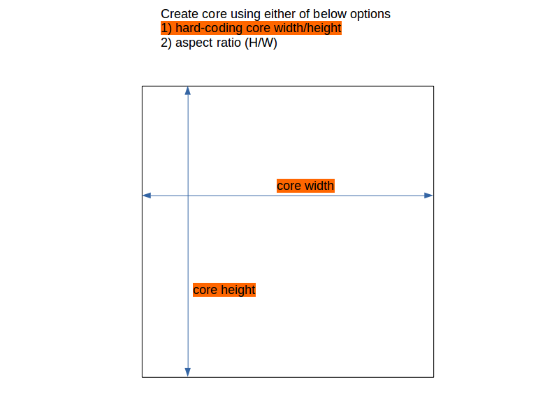
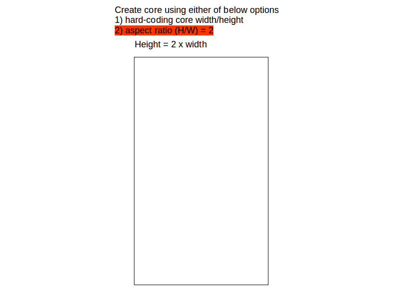
Step 2) Develop code (or command) to create core with either of below options (See below images for description)
- Hard-coding width and height OR
- Aspect ratio (height/width) and utilization factor
It can be a command something like below
create_my_core -width <number_in_um> -height <number_in_um>
OR
create_my_core -aspect_ratio <number> -utilization_factor <number_between_0_to_1>
If user gives -width/-height with -aspect_ratio/-utilization_factor, please issue an error
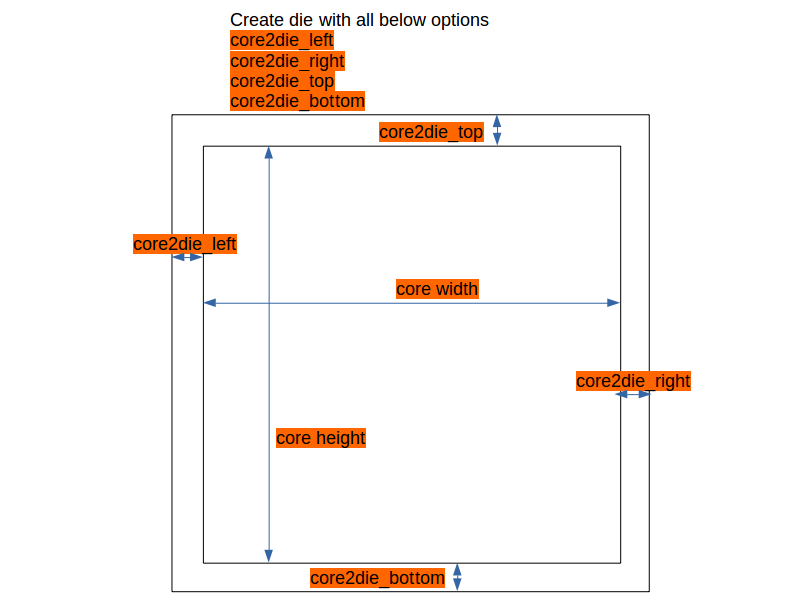
Step 3) Develop code (or command) to create die with below options (See below images for description)
- core2die_left
- core2die_right
- core2die_top
- core2die_bottom
It can be a command something like below
create_my_die -core2die_left <number_in_um> -core2die_right <number_in_um> -core2die_top <number_in_um> -core2die_bottom <number_in_um>
Terms and condition:
- You are free to use the source code of existing (and only) opensource tools like magic, qflow, graywolf, qrouter.
- Each line of your code needs to be open-sourced and documented.
