Combinational Logic
Logic is the process of decision making based on some conditions. Combinational Logic refers to the decision making combining one or many conditions. The entire decision making process when divided into fundamental decision making blocks, they become the basic logic gates which are And, Or, Not, Nor, Nand, Xor, X-Nor . All these decision are made based by associating Present/Absent or Yes / No or True/False to the individual conditions.
| GATE | Decision |
| NOT | Inversion . (i.e. Condition Not present) |
| AND | All the conditions are present |
| OR | Any of the conditions are present |
| XNOR | Equivality of Conditions |
| XOR | The conditions are Mutually Exclusive |
| NOR | Not even a single condition exists |
| NAND | Not all condition exists |
From this it is clear that any decision making , can be constructed from these basic decision making elements. For e.g. If you want to go for a movie, the decision will be made like follows. (Movie is Good or Friends with you want to go) AND (You are free time to spend for movie).
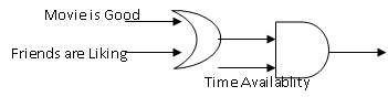
Here again the Movie is Good , is a decision collective of many factors, like The Star Cast is Good OR Screen Play of the movie is Good OR Story line of the movie is Good. Like this each condition can be further evaluated. This is a classical scenario of a decision making process. This is extensively used in the Digital circuit design as all the logical decision made in the Digital Domain are of the similar nature. E.g. If you want to create a logic to send some information to a receiver, it will be like The Information is available with you AND the Receiver is ready to accept the information. If this condition is met then you start sending the information.
Need for Sequential Logic
The above scenario of decision making, takes into account the present conditions existing only. This cannot be sufficient always to make a correct decision.
For e.g. If we consider the decision of a movie described above, You may want to go to a movie which you have not seen. So the decision will be made based on the present existing factors as described above and from your PAST, that is you have not watched the movie. The fact that you have not watched the movie can be considered as a state.
Which means you make a decision collectively based on the present prevailing conditions and the state you are existing.
Hence there is a necessity to store these state information as it should be made available for the future decision making. Here comes Flip-Flops which are basic 1 bit storage elements for this purpose.
Finite State Machine
From the example above, It is clear that the present state will be a factor for deciding the next state along with the present inputs. The same can also be told as the present state was derived from the past state with the present inputs. Both are same… it is just a play of words!!
So…the question is what is a state and how am I going to represent it ??
The answer is simple. States are different stages in the decision making process flow. In digital system, any information is represented or stored as 0s and 1s. So the states are also represented in a binary code in the form of 0s and 1s.
These 0s and 1s are in form of a code where each bit of 0 or 1 is coming from a flip flop.
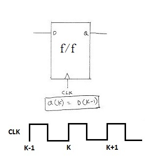
This entire information can be summarized in the below diagram.
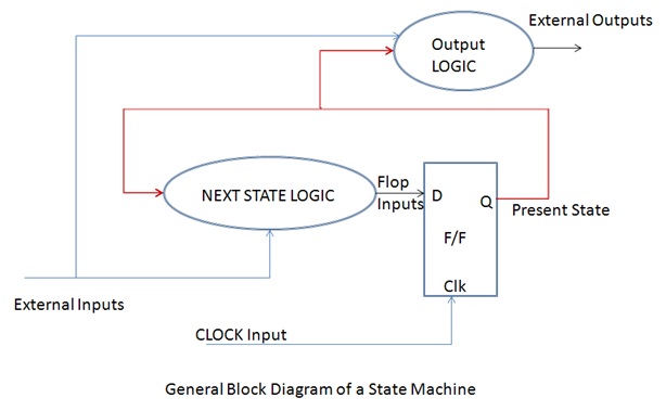
The F/F acts as a storage element to store the state information.
There is a decision making logic called the Next state Logic. It is to be noted that the inputs to the Next State Logic (NSL) are the present state (shown in brown) and the external input(shown in blue). Considering both, the decision for the next state is made. The decision made is latched by the flop on the clock edge.
So in our example, the “Movie not seen in the past” comes from the flop and the other inputs like the “Movie Reviews are good, etc ,etc” comes from the external inputs. Considering both the factors together the NSL decides whether to go to movie or not and this information is latched by the Flop on the clock edge. If the decision for watching the movie is taken the NSL generates ‘1’.. which means the flop input is now ‘1’ and the state is updated as “Movie Watched”…. So this will be a driving factor in the Next decision making process.
State Machine : A state machine is a digital system working on a predefined finite states. So they are also referred as Finite State Machine or FSM in short.
Case Study : Let us understand the need for a state machine and what it is based on a case study.
Let us consider the scenario of a 2 bit Up counter.
This machine is a counter which can count in the ascending (Up). The machine is a 2 bit machine. So it will need 2 flops (1 Flop per bit).
[Remember a machine having n flops can have 2n states (each flop can be 0 or 1 leading to 2n permutations)].
On reset the machine is at “00”. After reset the machine starts counting up on each clock edge. It will count as 00, 01, 10, 11 and after this again 00. So the states are finite and hence the name FSM. After this the states keep repeating in the same sequence. If I generalise the states as S0 , S1 , S2, S3 instead of 00, 01 ,10 ,11 … then the machine will be repeating the states S0, S1 , S2, S3 ,S0 ,S1,…… .
This can be diagrammatically represented in a diagram called the State Diagram. In the state diagram each state is represented by a bubble and the transition from one state to other is represented by an arrow. (The direction of the arrow is important as it shows from which state to which state the transition is happening. This is important because the Transition from S0 to S1 is totally different from the transition from S1 to S0 state).
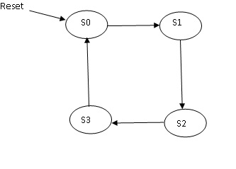
Please Note : Upon Reset the state machine is initialised at S0. This is very important. Upon reset any state machine has to be initialised to a Known Valid State.
Can there be an Unknown State ??
Ok Let us understand this clearly. There are 2 reasons why we have to define the reset state of the machine.
Reason1 :
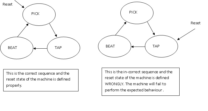
Let us take the example of a machine which will beat the EGGs and give us. Upon reset, the machine will pick up an egg, then tap it (break it) and take the yoke out of it in a bowl and then it will beat the yoke in the bowl. This is the sequence the machine is going to operate. (states are indicated in bold).
Now if upon reset I leave the machine in the tapping state instead of the Picking up the egg, Even without picking up an egg, it will try to tap it and break it. Two things can happen here, either the machine will wait for Egg in this state ( it has not picked the egg, so it will wait for the egg) and it will hang here or it will miss the sequence and something that is not expected out of it will happen.
So the reset state of a state machine is very important and must be defined clearly to a known valid state.
Reason 2:
Now let us take the example of a counter which needs to count 0 to 5, like 0,1,2,3,4,5,0,1,2,3,…. Upon reset the machine should be set to state 0( known state). What is a unknown state then ?? Ok …..From the implementation point of view …there are six states in the machine and we need 3 bits for implementation. But a machine which has n bits will have 2n states which means here there are 8 states. But we are designing the machine to operate only in 6 states(0 to 5). Which means there are 2 unused states (6 and 7) or undefined states for the machine. The machine will not know what to do in this state as we have not designed it for these states. So it will hang or preform some totally unintended operation.
This can be very serious….For eg. Let us take a case of a digital system which is used for Missile Control.
There is a state machine which decides when to fire the missile. Suppose the machine goes to undefined state and fires the missile in the own base itself!! …It is comedy to read it here but in real life it will be a tragedy!!!!!
So a good designer should always provide a means to initialize the machine in known state and if there are unused state and it is enetered because of some error conditions…there should be a way to reach the initial state. Else it will be disastrous!!.
State Transitions:
The change from any state to its corresponding next state is called a state transition. The transition from one state to another state can be a conditional transition or an unconditional transition.
What does this mean…?
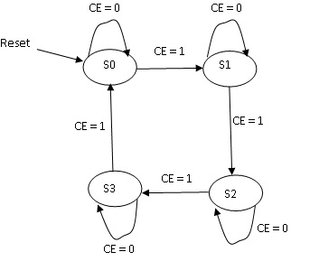
Let us understand it with an example. Let us take the scenario of the same 2bit counter, The intent is to count only when the Count_Enable is high, Else the counter should retain its present state.
Now how to represent this scenario in the state Diagram…..Now from the given scenario it is very clear that the transition from the state is based on a condition [Count_Enable = 1] , these type of transitions are called Conditional Tranisitions in a State Machine. The Transitions which we saw earlier are Unconditional Transitions. The Unconditional Transition can occur on every clock edge, but conditional transition can happen on the edge of the clock where the condition is met.
Let us see , how this diagram looks. (the Count_Enable signale is shown as CE in the state diagram below)
Now let us complicate the situation and see. In the above scenario there is only one condition for every transition. But there can be more than a single condition to decide the transition from one state to another. The counter is a 2 bit Up-Down counter with Enable. When the counter is Enabled it should count Up (Ascending order) or Down (descending order) depending upon the UD signal. If UD = 1, it should count up and if UD = 0 it should Count Down.
So the state diagram has to accommodate these conditions also….
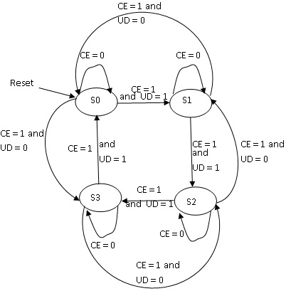
From the state diagram it is clear that when the Count Enable (CE ) is low, there is no transition in state irrespective of the value of Up-Down (UD). Hence the value of UD is NOT indicated in these cases.
Whereas the value of UD is considered to Count Up / Count Down when CE = 1. Hence for the transitions when happening CE = ‘1’ is indicated with the value of UD.
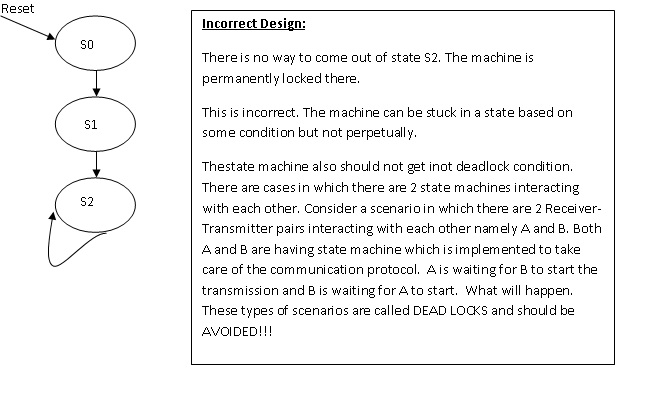
Please Note : The state diagram is a closed diagram…meaning the path from any bubble to any other bubble is a closed path. There should not be any state where the machine gets dead-locked , also there should not be any state for which the next state is not defined.
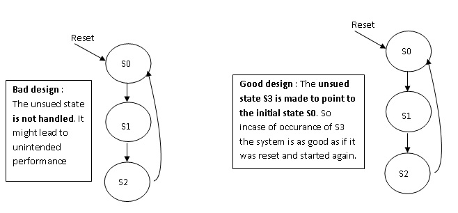
Example of a state machine with unused state :
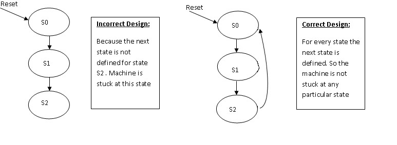
Let us consider the case of a state machine having 3 states (S0 , S1, S2). Let S0 be the initial state. There are 3 states, which means we need a minimum of 2 bits per state, else it is not possible to have 3 states.
But if the states are represented in 2 bits, then there will be 4 states, which means that there is one unused state. Now the machine should not enter this state under no circumstances. In case if it enters because of some malfunctioning, it should not be stuck up there. How to do this ???
This will be done by redirecting the state from any of the unknown state to a known initial state. (Note:: We have to point to the initial state, because we might not know if we go to some other state, it might not be meaningful…!!! Will elaborate this below).
When the state machine lands in a unknown state, then it is a corruption of state. This cannot happen in the normal working condition of the state machine, because the machine is not designed to land in this state. But then how it can land in this state ??? Ha! That’s the point to understand. That’s why I mentioned it as corruption of state earlier. That is because of one or more state bit got flipped from 1 to 0 or vice versa due to some noise or disturbance in the sorrounding. But there is no mean to say which bits have got flipped. This means we cannot say from which state we landed here. So the best thing to do under such scenario will be to start from the initial state.
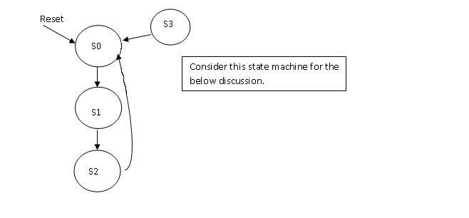
Confused??!! Ok …let me elaborate it. Consider the above state machine. Let S0 be “00”, S1 be “01” and S2 be “10”. Let S3 be “11” which is the unused state. Now there is a transition from state S1 to S2 that is the state bits are changing from 01 to 10, but because of some noise and error it became “11” which is state S3(here unused state) or it may also happen while changing from S2(10) to S0 (00) it got errored to S3(11). There is no way to say from which state we ended up in S3 as this is not defined for this machine. We can say that we reached S2 from S1, but we cannot say from where we reached S3. So it is always better to reset it.
Now you may ask me, that whatever I am talking above can happen with used states also. That is while changing from S0 (used state) to S1 ( another used state) there was error so it went State S2. Yes it is quite possible and the state machine will fail to perform the required function. Now how to take care of this?
For understanding the above point we need to understand the exact application of the state machine as to where it is used and how to implement a proper state machine.
Ok…let me not build too much suspense. From the discussion so far one thing is clear. The state machine is a very good way of implementing decisions. That is using a state machine, the decision is made using not only the present inputs but also based on the past state. So the best application for the state machine is for decision making process. State machines can be used for much bigger complex decision making process…basically they become the core of the control logic (Brain) of a digital system.
HOW ??????
Let us understand this point with a real life example
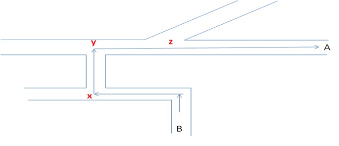
Consider the map shown above. Assume that you are standing at point B and you have to travel to point A. It is very simple. You travel as shown take a right turn at point x and y and at junction z you donot turn and move straight. It is not as simple as it appears. You reach A from B if and only if You did not miss the turn x, made a proper turn in required direction at y and by not making a turn at z.
Now let us relate the same to a digital system. Let us now think A and B as some buffers in a system. The path is shown is a connection say a Bus. Now data from B has to be sent to A . The information should take the same path as shown in the map. But the data is not having a brain like us to think as to where to turn and where not to turn. So the data from B has to be sent to A and only to A.
How will this happen ?
There has to be some logic, to steer the information from B to A. It should also take care to prevent the information not going to undesirable places.
The notion of Data Path and Control Path in a Digital System:
With reference to the above example, the path in which the data traverses in a digital system is called the Data path. Now the data to travel in the desired path and to perform the required operation on data there needs to be some other signals generated. These are called the Control Signals. These are generated by the state machine. Hence the state machine is referred to as the brain of the digital system.
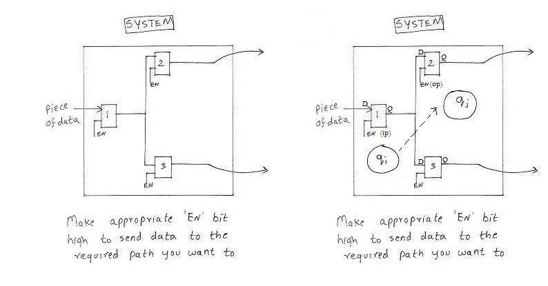
The same is explained in the figures above. The data from register 1 has to be moved to register2. This is done by enabling the register1 and register 2 and more important by not enabling register3 . Thereby we steer the data from register 1 to register 2. This can be associated with a state change as shown above from state Qi to Qj.
Let us do a case study.
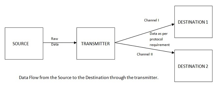
Let us discuss about a transmitter. The block waits for the data to transmit. The requirement is, it takes the data from the source and transmits it to destination1 or destination2 based as requested by the source. It should notify the sender to wait till it finishes the transmission before the sender can put a new data (else the data will be missed). The sender gives only the data. The transmitter takes care of generating the start and stop bits before the start of transmission and after the transmission is over. Basically the transmitter takes care of the protocol to be followed.
Let me describe this pictorially.
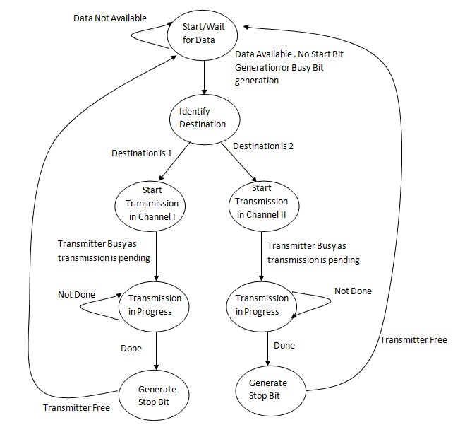
Here we realize the actual power of the state machine. The requirement was to move a data from Source to Destination1 or Destination II. But we see that there are lot of auxiliary signals required at different instance to complete the task. The state machine comes handy in these situations.
Back to Floorplan
Back to Introduction to Industrial Physical Design Flow
