- Make sure your C drive or D drive has atleast 100GB space (as shown in Fig 4)
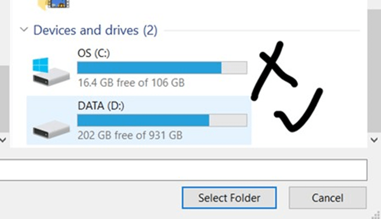
Figure 4: Diskspace check
- Download VSDSquadron FPGA Mini (FM) Software on your laptop
- Unzip the downloaded file and follow the below instructions
- Download and install Oracle VirtualBox on your Windows computer if you haven’t already.You can download it from the official website
- Launch VirtualBox and click on the ”New” button to create a new virtual machine. Fill up the details exactly as highlighted in RED as shown in the Fig 5.
- In the ”Create Virtual Machine” wizard, enter a name for the virtual machine and select the operating system type as Linux and version as Xubuntu (64-bit) that matches the one installed in the VDI file you want to open. And then click on ”Next”
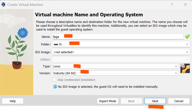
Figure 5: Virtual Machine Launch
- On the next screen, allocate memory as 4GB (or 4096 MB) and number of CPUs as 4, as shown in Fig 6. Then click on ”Next” button
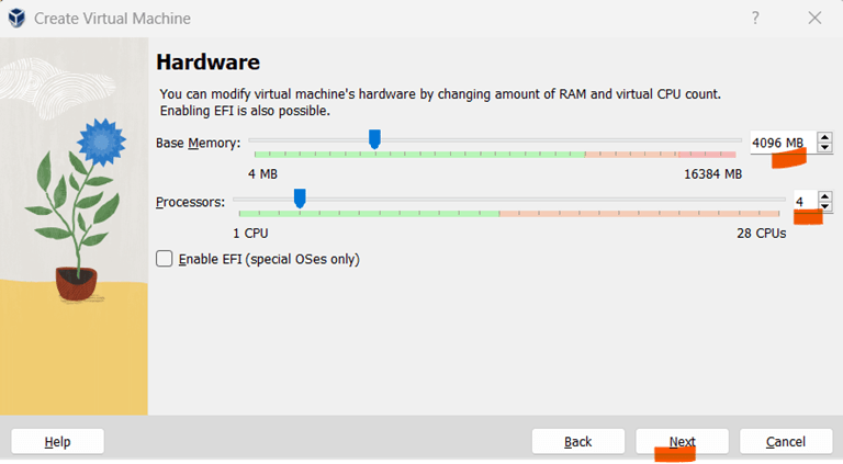
Figure 6: Allocate RAM and Number of CPUs
- Create a virtual hard disk. Choose the ”Use an existing virtual hard disk file” option and click on the folder icon to browse to the location of the unzipped VDI file on your Windows computer as shown in Fig 7. Once done, click on ”Next”
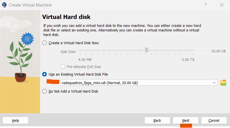
Figure 7: Choose VSDSquadron FPGA Mini VDI
- Click on the ”Finish” button as shown in Fig 8
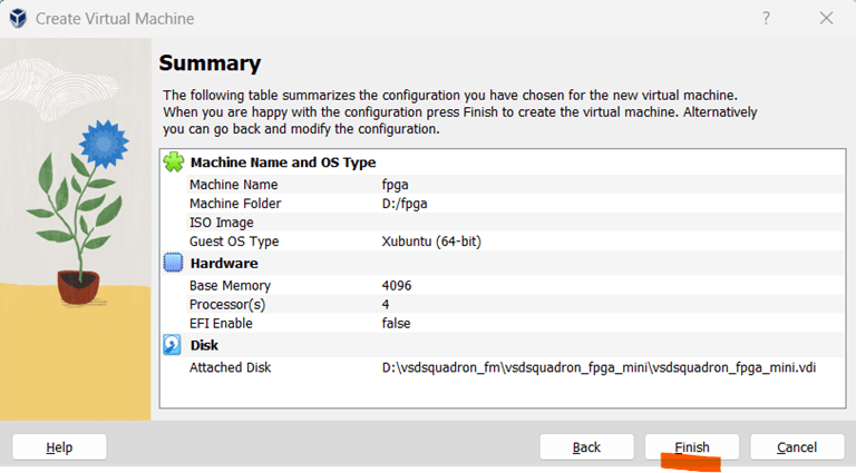
Figure 8: Finish Setup
- Once the virtual machine is created, select it from the list of available virtual machines in the VirtualBox Manager and click on the ”Start” button to launch it, as shown in Fig 9. It would take about 2-3 minutes to start the virtual machine
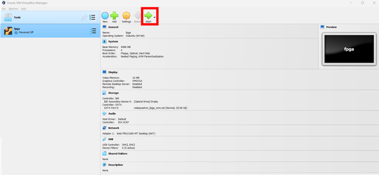
Figure 9: Start virtual machine
- The VM will start and prompt for password as shown in Fig 10. Enter the password as ”vsdiat” and click on ”Log In” button
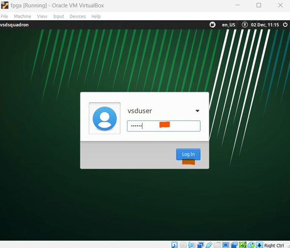
Figure 10: Enter Password
- You will see a window as shown in Fig 11. Take your cursor in the middle of the screen and right click on mouse. You will see lot of options as shown in same Fig 11. You need to left click on terminal as marked in RED in below Fig 11
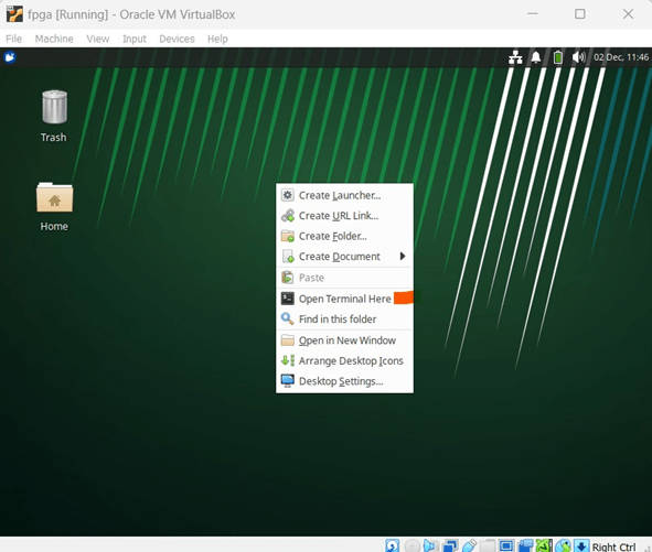
Figure 11: Steps to Open Terminal
- You should see a terminal window as shown in below Fig 12
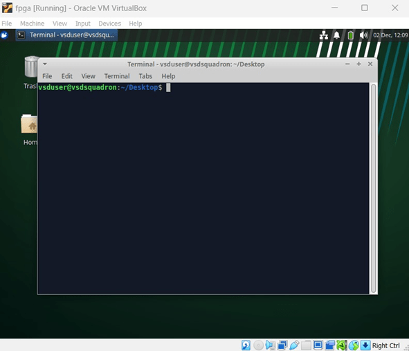
Figure 12: View Terminal
Let’s start our first project. To navigate through project directories in a UNIX environment,
use the following commands:
cd
cd VSDSquadron_FM
cd blink_led
The commands above allow you to:
– Change to the home directory (‘cd‘).
– Navigate to the ‘VSDSquadron FM‘ folder, which has a sample project.
– Move into the ‘blink led‘ directory, which is the first FPGA project to be tried on VSDSquadron FPGA Mini (FM) board.
Refer to Fig 13 for more details
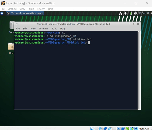
Figure 13: Navigate through project directory
There is a preloaded project in ”blink led” directory. To test the project on VSDSquadron
FPGA Mini (FM) board, we need to make sure that the board is connected to the Oracle
Virtual Machine. Perform below steps
– Connect the board to your PC, as shown earlier in Fig. 3.
– On the Virtual Machine, click on ”Devices → USB → FTDI Single RS232-HS [J900]” as
shown in Fig. 14.
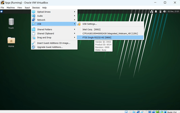
Figure 14: Connecting the Board to USB
– To confirm if the board is connected to the USB, type the ‘lsusb‘ command in the terminal.
You should see a line stating ”Future Technology Devices International,” as shown in
Fig. 15.
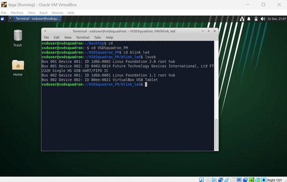
Figure 15: FTDI Message from ‘lsusb‘ Command
- To program the VSDSquadron FPGA Mini (FM) board, follow these steps:
– Run the following command to clean up previous builds. Refer to Fig. 16:
make clean
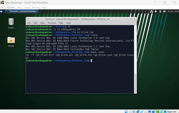
Figure 16: Output Screen after ‘make clean‘ command
– Build the binaries for the FPGA board using below command. Fig. 17 shows the output
screen after ‘make build‘ command:
make build
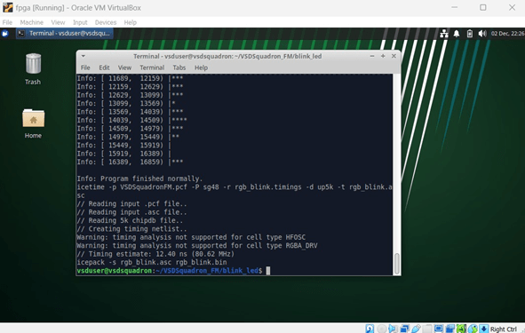
Figure 17: Output Screen after ‘make build‘ command
– Flash the code to the external SRAM with the following command:
sudo make flash
– After executing the above command, the screen will look as shown in Fig. 18.
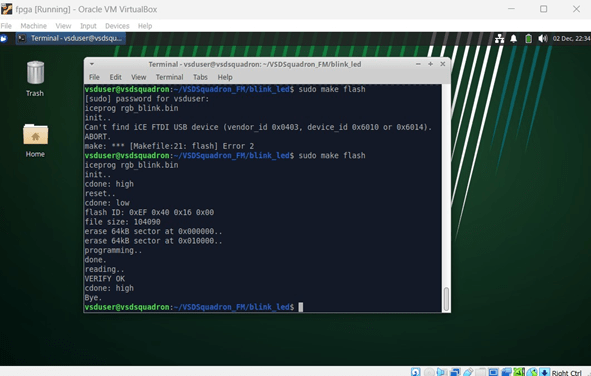
Figure 18: Output Screen after Flashing the Code
– Note: If you get an error as shown in Fig. 18, then probably the board got disconnected.
Try repeating the step as shown in Fig. 14
– Once the code is successfully flashed, you will see the RGB lights on the FPGA board
blinking.
