Hey There – Think about it…!!
Problem Statement – For hierarchical designs ~500k instance count, participants are expected to develop code which will modify existing clock tree routes with non-default rules for selected nets
Inputs given for code development and testing:
- A text file in DEF format with clear definitions of core/die width, pad placement, pre-placed cells, power rings around core/pre-placed cells, clock tree buffers/routes and other information unplaced/placed/fixed cell with locations of all flip-flops and combinational cells
- A netlist in Verilog format corresponding to above DEF
- Industry grade 180nm PDK’s (standard cells, memories, pads) LIB and LEF formats
Expected output:
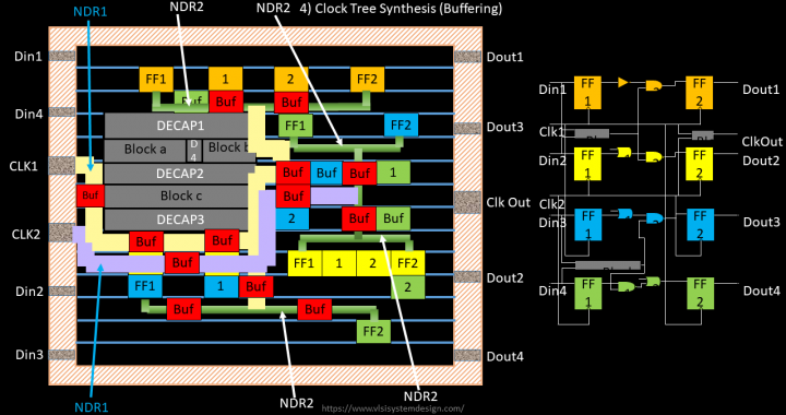
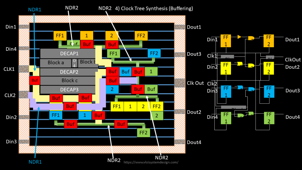
A text file in standard DEF format and Verilog netlist which has all information about inputs which were provided + information about clock tree routes with non-default rules for selected nets (shown in below image)

In principle, the output and qualification criteria are shown in below image
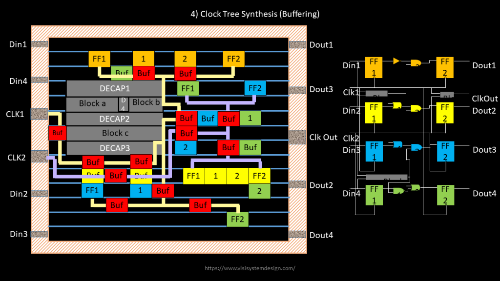
Step 1) Find a way to parse input DEF file and verilog file provided by VSD, which has locations, co-ordinates, instance names, connectivity details and many more information of all instances that you see in below fig. It can be a command something like below
read_def <input_def_file>
read_verilog <input_verilog_file>
If the DEF file syntax is not in par with standard DEF syntax, issue an error message specifying line number where there is a syntax error. Same with verilog syntax
Step 2) Develop code (or command) which will enable users to create non-default rules, something like below. Refer to default rules from tech lef, which will be a good starting point
create_my_ndr -name <non_default_rule_name>
update_my_ndr -name <non_default_rule_name> -width <double_or_triple_width> -spacing <double_or_triple_spacing> -layer <layer_name>
User can use the above commands, like below
create_my_ndr -name ndr1
update_my_ndr -name ndr1 -layer m1 -width 0.5 -spacing 0.7
update_my_ndr -name ndr1 -layer m3 -width 0.8 -spacing 1.0
create_my_ndr -name ndr2
update_my_ndr -name ndr1 -layer m1 -width 0.25 -spacing 0.35
update_my_ndr -name ndr1 -layer m3 -width 0.4 -spacing 0.5
Step 3) Develop code (or create command) to report newly created NDR’s, something like below
report_my_ndr -name <ndr_name>
User can use above command like below
report_my_ndr -name ndr1
Output:
my_ndr_name “ndr1”
layer_name:width:spacing
m1:0.5:0.7
m3:0.8:1.0
Step 4) Develop code (or command) to “route leaf cell + 1 level buffer route output + same buffer input till branch-off point with ndr2” and “route other clock nets with ndr1”
It can be a command something like below.
special_route_clock_nets -leaf_cell_clock_net ndr2 -other_clock_nets ndr1
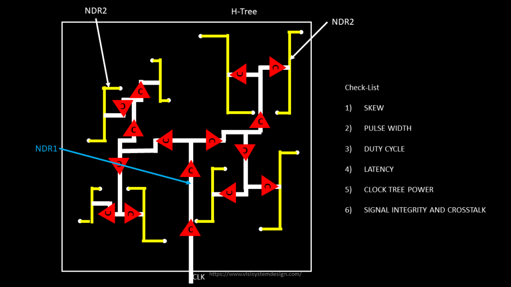
Step 5) Clock tree quality will be checked for skew, pulse width, duty cycle, latency, clock tree power and crosstalk coupling as shown in below image

Terms and condition:
- You are free to use the source code of existing (and only) opensource tools like magic, qflow, graywolf, qrouter or any other
- Each line of your code needs to be open-sourced and documented
