The dimensions of interconnects (wires) scales down, as VLSI technology scales down by a factor called as ‘scaling factor (s)’. The scaling factor is an integer by which the dimensions of interconnects shrinks down. Typically, the resistance, capacitance and inductance are the 3 main factors of wires that is affected by scaling. Following sections will explain how each factor gets affected by scaling, and concurrently, its impact on system.
Resistance:
Wires are usually classified as ‘short’ and ‘long’ wires. Lengths of short wires are scaled by a scaling factor ‘s’, whereas lengths of long wires are independent of scaling. ‘Short’ wires are typically used for local communication between gates that are placed with minimal distance, whereas ‘long’ wires are used for long range communication at the different corners of chip. Power supply rails can be an example of long wires.
Consider the below diagram, which shows how resistance scales for ‘short’ and ‘long’ wires.
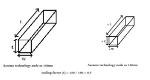
Assume, the gate length (node) is shrinking from 180nm to 130nm. The factor with which the gate length scales down is ~0.7 (i.e. 130nm / 180nm). Hence, s = 0.7 (approx.). Consider a short wire as shown above. For a short wire, all 3 factors (i.e. length, width and thickess) scales down by the same factor i.e. 0.7. Hence, as per above equations, due to scaling, the resistance of a short wire increases by 1.42.
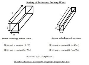
On the other hand, for long wires, where the length of wire is independent of scaling, only thickness and width of the wire scales down. Hence, as per above equations, the resistance of long wire increases considerably by 2.04.
Capacitance:
In 5um technology, the width of the wire would be, say, 10 um and thickness, say, 1 um, as shown below :
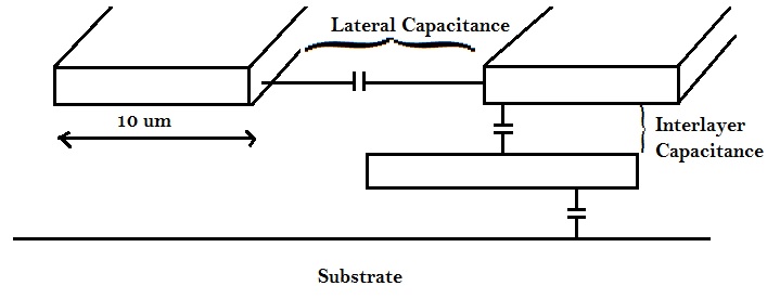
In the above 5um technology, the dominant capacitance, was the parallel plate capacitance between adjacent layers, i.e. inter layer capacitance. The lateral coupling capacitance’s i.e. capacitance between two conductors on the same plane, exists, but ineffective.
Consider the below diagram, which shows how capacitance scales for ‘short’ wires.
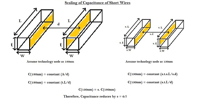
In case of short wires, all the parameters of wire scale down. Hence the capacitance goes down by the scaling factor i.e. 0.7, as per equations shown in above diagram.
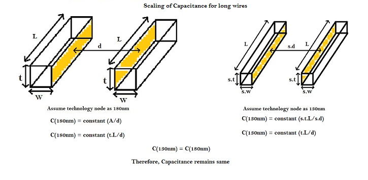
In case of long wires, all the parameters of wire scale down, except its length. Hence the capacitance remains same, as per equations shown in above diagram.
RC Delay:
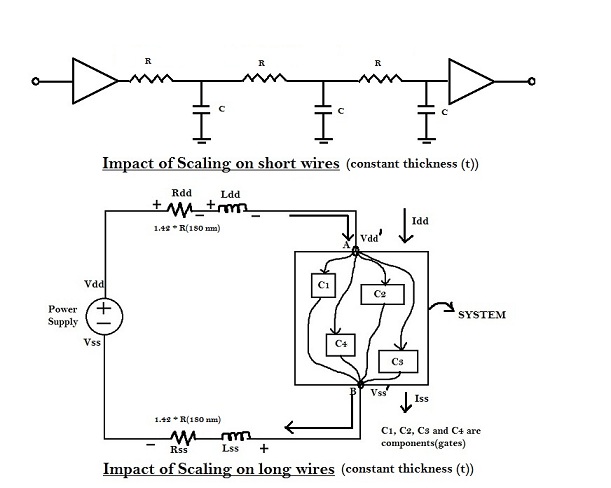
Figure below shows the impact of scaling of short and long wires on RC delay.
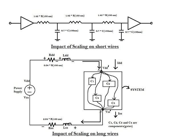
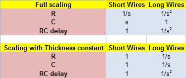
For short wires, ‘R’ scales by (1/s), whereas ‘C’ scales by (s). Hence, the RC delay for short wires is unaltered, which means that the capability of short wire to transmit high frequency signals,is same.
But, for long wires, ‘R’ scales up by (1/s2), whereas the capacitance remains the same. Hence, the RC delay for long wires increases by (1/s2). If s = 0.7, then RC delay increases by 2.04. If long wires are used for power rails, it would affect the noise margin of the circuit. Also, if long wires are placed between two logic cells, the RC delay between the cells will increase significantly, which may lead to potential setup violation.
This trend of increased RC delay with scaling, combined scaling trends of ‘R’, which increases by (1/s2), decreases the ability of long wires to transmit high frequencies.
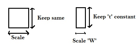
An optimal solution is not to scale all dimensions of the wire as shown in diagram below.
Considering the above trend of keeping ‘t’ constant and scaling only ‘W’, the resistance of short wires scales as shown in diagram below .
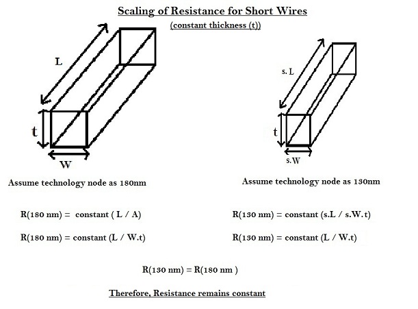
Thus, for short wires, with thickness kept constant, the resistance remains same. Similarly, for long wires, the scaling of resistance is as shown in below diagram.
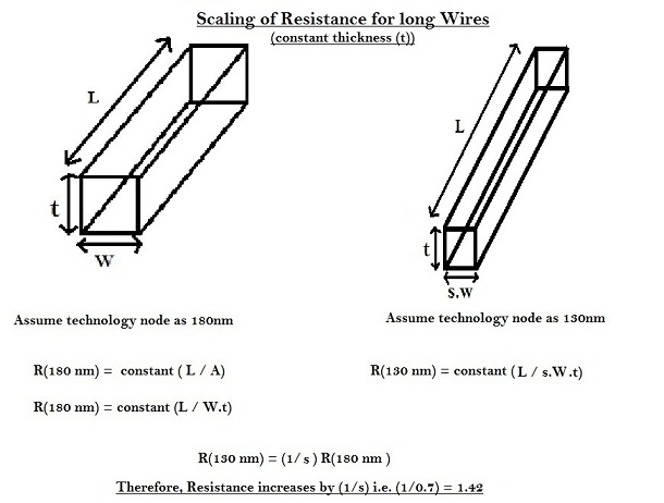
Thus, for long wires, with thickness constant, the resistance increases by (1/s) as per equations shown in above diagram.
Similarly, for capacitance, the effect of scaling wires with constant thickness is shown below
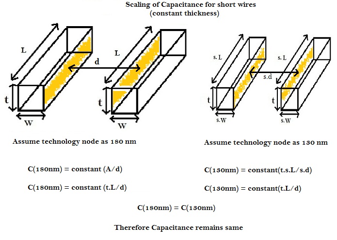
Thus, for short wires, with thickness kept constant, capacitance remains same.
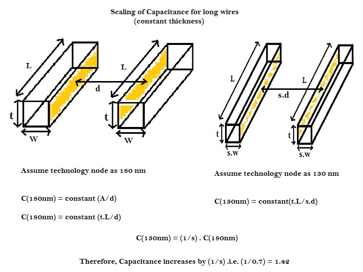
Thus, for long wires, with thickness kept constant, capacitance increases by 1.42, as per above equations
As shown in above figure, there is no impact on RC delay with thickness of wire kept constant.
Scaling Summary
In certain cases technically, the thickness can’t be changed, and ‘R’ has trend of ‘constant’ for short wires, and (1/s) for long wires. To further reduce the resistance of wire, the only variable availed for scaling is ‘width (W)’ of wire. As the width of the wire increases, resistance decreases, but the routing density of wires in the specific layer increases. To reduce the routing density of a specific layer, due to wide wires, the number of layers, to make contacts between signals, has to be increased. Earlier (in 1985), 2 metal layers were sufficient to make all signal connections on a silicon chip. With current scenario, 7-8 metal layers are used for same. Proportionately, 10% of metal layers are used only for power and ground supply.
